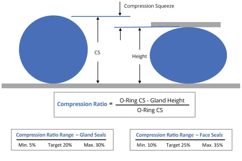
An oring acts as a seal by blocking any potential leaching path, of a liquid or gas, between two closely matted surfaces An oring is installed in a machined grooved gland (see gland design for examples) in one of the two surfaces to be sealed As the two surfaces are brought together the orings cross section becomes deformed producing a tight seal, see image The greater theFastDash TM Oring Piston Seal Design Guide Enter the "A" diameter (ie bore diameter), Press the "Submit" button, The appropriate dash no orings will be listed along with their associated groove details BackUp Rings req'd None 1 2 "A" Diameter inches Oring CrossSection Selections103 in139 in210 in Dash No Act ID Dash No Act ID Dash No Act ID GrooveDesign Chart 7 shows the groove width necessary to accommodate the thickness of the backup rings Teflon backup rings are usually furnished in single or dual turn rings Single turn rings conform to MS and match the standard PAI Oring sire Dual turn rings conform to MS 287 and match the dash numbers of an AN 6227 series of Orings MS 287 backup rings

O Ring Groove Design Seal Design Inc
Seal groove design for o ring
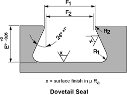
Seal groove design for o ring-Glossary of ORing Terms;As shown in above figure, an Oring also gets compressed axially in a dovetail groove The groove design allows the Oring to be retained in the axial/face seal during assembly and maintenance This is beneficial for special applications where the Oring has to be fixed by the groove eg a lid which opens regularly
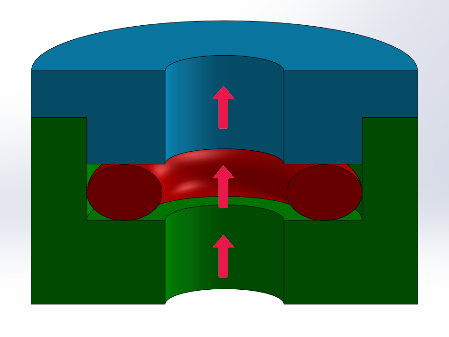


4 Common Mistakes In Designing For An O Ring Axial Face Seal Hot Topics
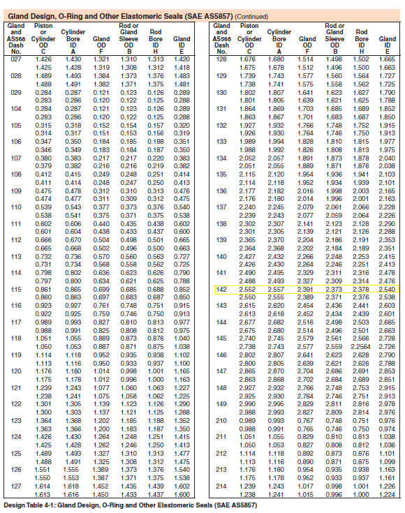
Call Us Seal & Design Canada Toronto, Ontario (416) Toll Free Headquarters Clarence, NY (716) Higbee Division Syracuse, NY (315) Email Us Seal & Design Canada Toronto, OntarioOring Gland Design Dovetail seal Also here there is a metal to metal contact as long as the construction will not deform under system pressure (fig 130) Boss seal The groove dimensions are incorporated in the standard dimensions Surface Finish Static Grooves Straightsided grooves are best to prevent extrusion or nibbling Five degree sloping sides are easier to machine and areOring Groove Design in 3 easy steps Step 1 Choose whether you are working with existing hardware or designing new hardware Select the type of Oring groove piston, rod, face seal or trapped seal If the Oring size required is known, simply select the AS, BS or ISO standard (such as AS568) and enter the dash size reference If the Oring size is unknown, input the nominal
Now, follow the steps below to design your own oring seal and oring groove Step 1 Choose your rubber properties by going to our Oring Material Guide section Step 2 Make sure that the material you choose will withstand the temperature of your system by going to this rubber temperature range chart Step 3The Oring is also axially squeezed in a dovetail groove The groove design allows the Oring to be retained in the face seal during assembly and maintenance This is beneficial for special applications where the Oring has to be fixed by the groove eg a lid which opens regularly Bosstail The Oring is used for sealing straight thread tube fittings in a boss A boss is aClick here for more information on face seal groove design Note the ORing inside diameter for the next step Calculate the Seal Stretch Using Equation 1, calculate the installed seal stretch If the installed seal stretch is greater than about 3%, you may have to select the next larger ORing or require a custom ORing for your application If you are using an ORing size less than a number
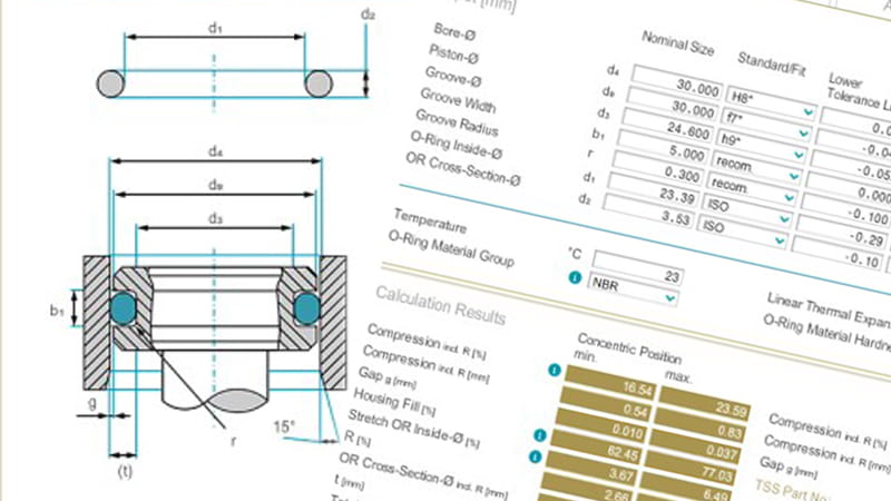
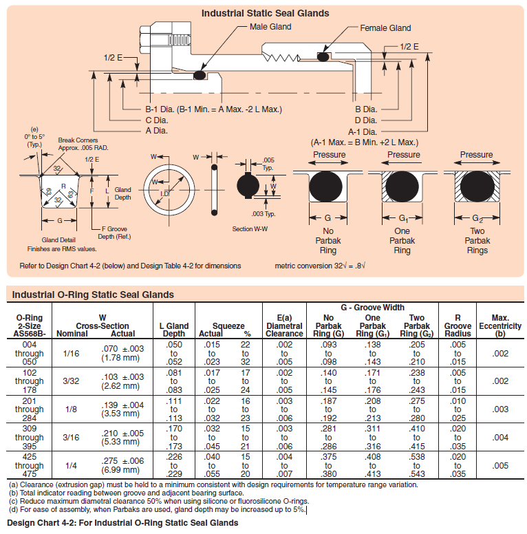
Oring installation dimension Please choose the particular value/measurement in the according box You can choose either a special cross section, groove depth or groove width All other parameters will be generated automatically All data in millimetre Errors and amendments accepted The declared values are not binding and can not be contested10 ORING SEALS – THEORY AND DESIGN PRACTICES Theory An oring seal consists of an oring and a properly designed gland which applies a predictable deformation to the oring The gland is basically a groove dimensioned to a certain height "H" and width "W" (Figure 1) to allow a fixed compression of the oring when the gland flanges make metal to metal contact It is alsoNote Due to effect of centrifugal force, do not locate groove in shaft Refer to Design Chart 54 (below) and Design Table 54 for dimensions Rotary ORing Seal Glands, 552 Bar (800 psi) Max (c) (Below 0 FPM, Use Design Chart 52) ORing Size Parker No 2W Cross Section Nominal Actual Maximum Speed FPM (a) Squeeze % L Gland Depth G Groove Width E (c) Diametral


Dovetail Gland Design Dovetail O Ring Groove Dovetail Glands
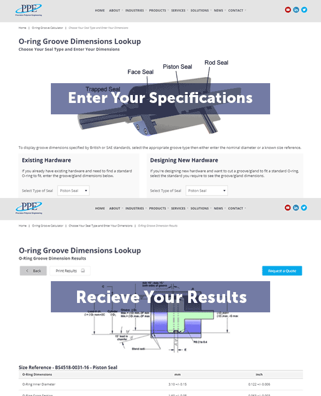


O Ring Groove Dimensions Calculator Precision Polymer Engineering
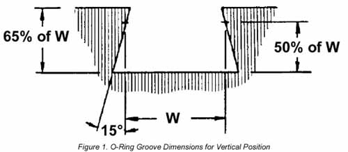
ORing Groove design plays an important part in how an oring seals Learn More > Contact World Class;Find Orings by size, temperature range, material type, compliance, and more Find and Buy Marco Orings Online *Recommended surface finish Ra 16 max for gases and Ra 32 max for fluids Static ORing Gland Width and Depth and Diameter Default Recomendations AS 568A SeriesTested in face type Oring seals using grooves that provided 15%, 30% and 50% compression For vertical Oring applications (as a chamber), it is desirable to use an undercut groove similar to that shown in Figure 1 The Oring is held firmly in place and has no tendency to drop out of the groove when the chamber is open Figure 1 ORing Groove Dimensions for Vertical Position Pressure
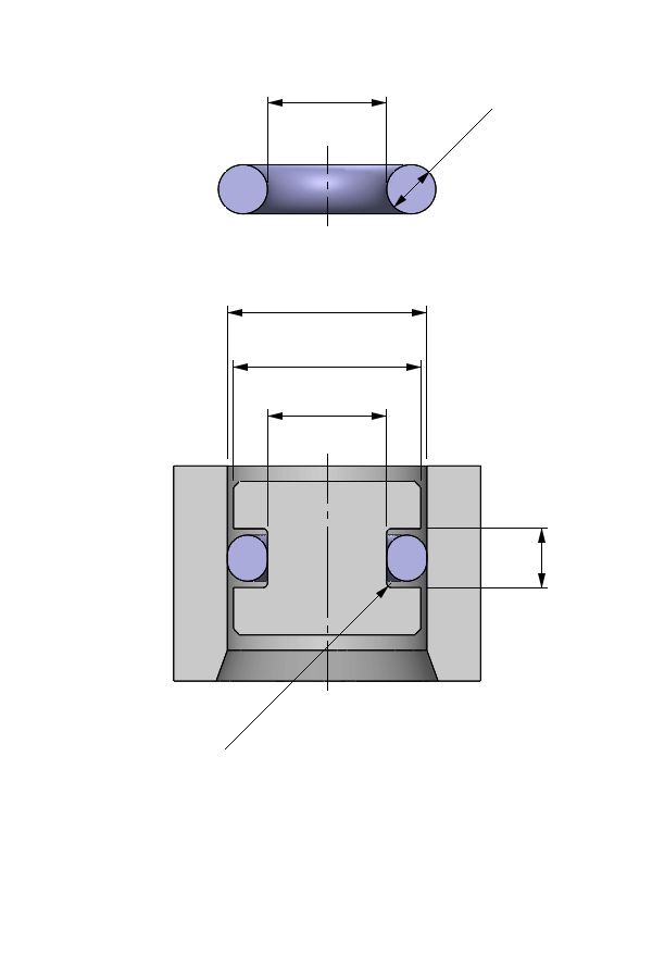


O Ring Calculator Ceetak Sealing Solutions
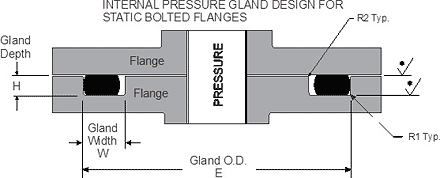


Static O Ring Face Seal Groove Design Guide
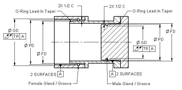
1 Male or Plug the Oring groove is located on a plug which is inserted into the housing or cylinder (fig 123) 2 Female or Tube the Oring groove is located in the housing or cylinder and a tube is installed through the Oring lD (fig 124) Male or Plug Seal design is based on the following factors (refer to fig 123) BoreERIKS standard ORings and load them also into your created design info chemical volume swell (%) cross section diameter (mm) ISO 3601 free Calculate Results Reset calculatorMust be incorporated in the design resulting in wider grooves If these factors are not known, you will have to make a more general assessment So select the largest section 'O' Ring to fit the nominal groove diameter This will tolerate the widest range of metalwork size differences, surface defects and high temperature Consider how the 'O' Ring is to be fitted a 5% stretch is


O Ring Groove Design Seal Design Inc


O Ring Groove Design Seal Design Inc
On the flip side an External Groove, (aka a male gland) the design will be based on the minimum bore diameter that the oring will seal against This is the first number that is needed The second number that is required is the Oring Series that you want to use This will drive the rest of the design The rest is plug and play and easy programmed into an excel file or similar programThose who are already familiar with Oring seal design may simply refer to the appropriate design tables for the information needed Even those who have designed many Oring seals may profi t by reviewing the basics from time to time 11 What is an ORing?Be it dynamic or static operation, radial or axial loading, vacuum or high pressure The following information is a guide for o'ring groove dimensions for both static and reciprocating
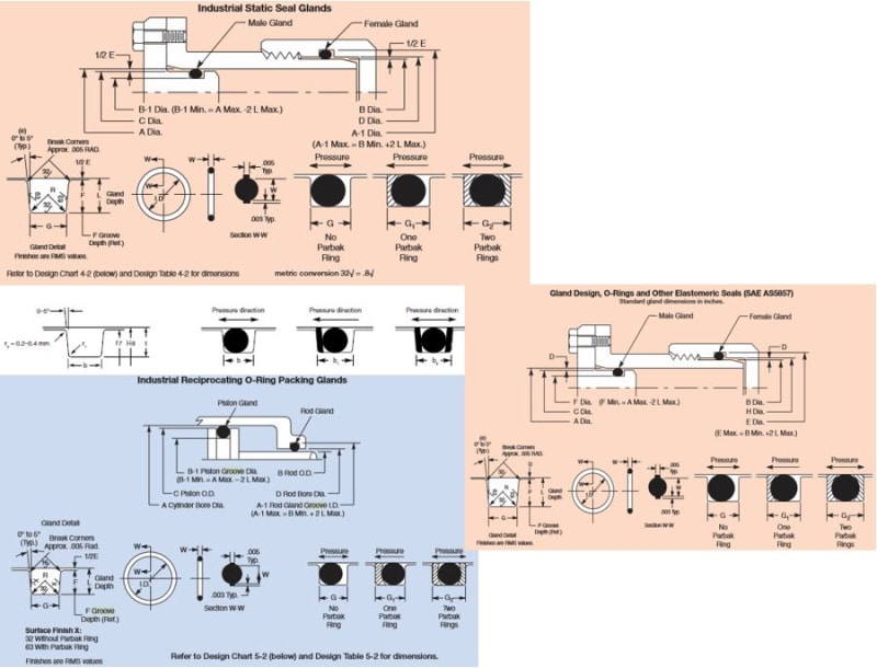


O Ring Groove Drafting Standards Gd T Tolerance Analysis Eng Tips
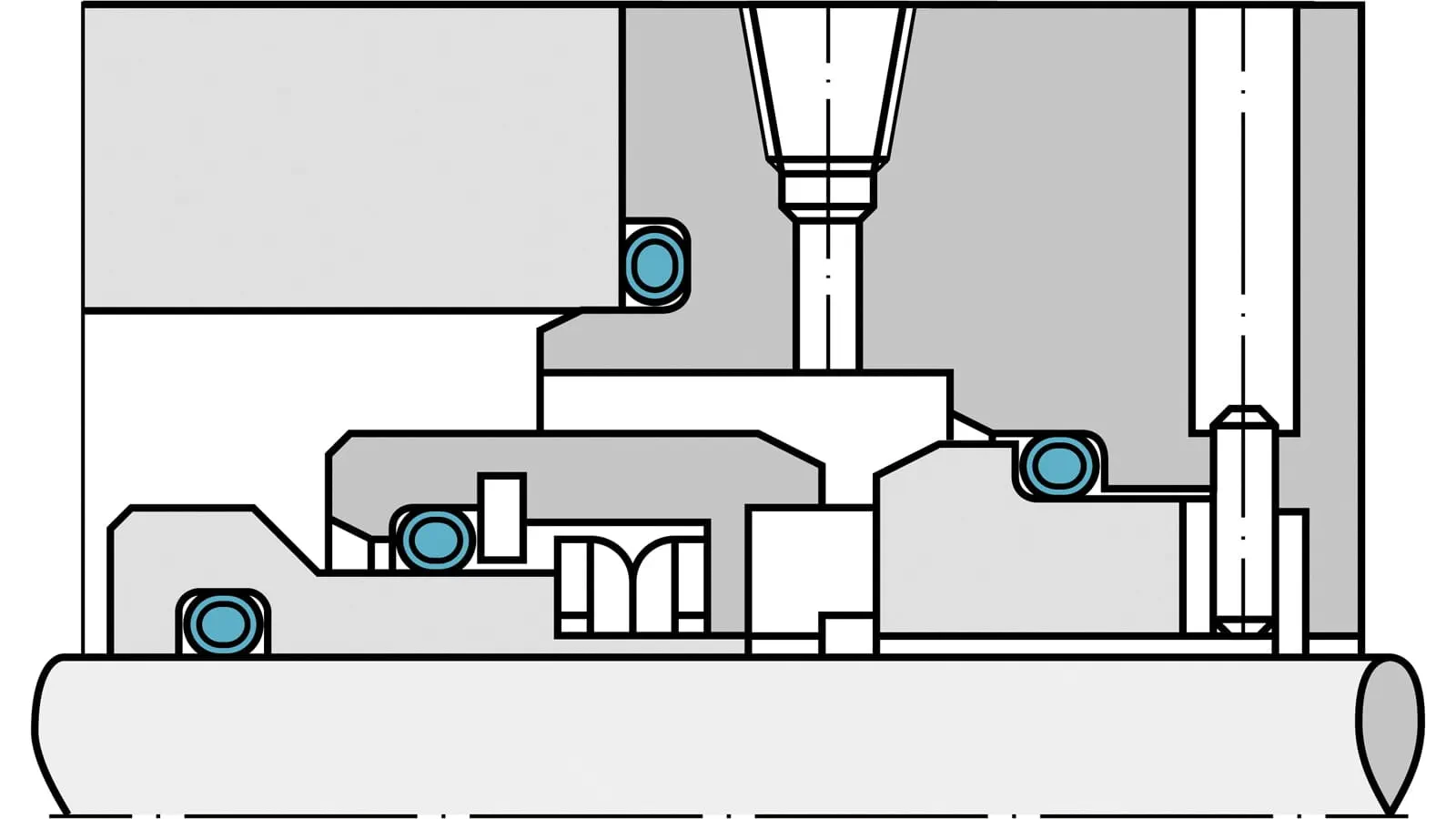


Fep O Rings Trelleborg Sealing Solutions
Groove Design Chart for QuattroSeals® Groove Design Chart for PTFE ORings Static ORing Glands Dynamic ORing Glands Literature Download Request a Quote Grooves for PTFE ORings are similar to those for rubber ORings, except that less squeeze is applied, due to the relative stiffness of the material Also, the groove width is generally less, as PTFE Orings are much lessGroove Design ORing Seals for Static and NonRotary Dynamic Applications Crosssection Select an ORing crosssection size from the available standard sizes If you are unsure what crosssection size to use, see here Clearance Determine the maximum clearance present in your application For a radial seal, subtract the minimum rod (shaft) diameter from the maximum boreThe original design used a oring, that is one 239" ID x 070" cross section The correct radial groove space for this would be about 063" (the 007" difference used for squeeze), but it had, somehow, ended up at about 070" And while it was a static seal, it was going to be installed first in an oring groove on a plug and then


O Ring Groove Depth T O Ring Groove Width B Radial An Axial O Ring Fitting



O Ring Groove Calculator O Ring
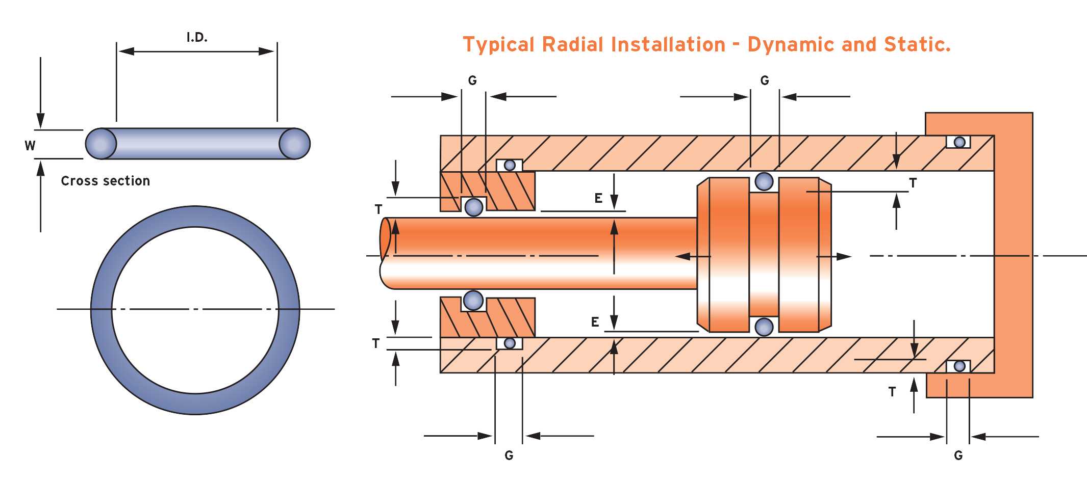
An Oring is a torus, or doughnutshaped ring, generally molded from an elastomer, although Orings are also made from PTFEShelf Life and Storage;The oring gland design is more complex for radial seals and requires both the piston and the bore to have precise geometry The bore and the piston have to be concentric to one another One of the faces will be completely smooth and one will have an oring groove cut into it;
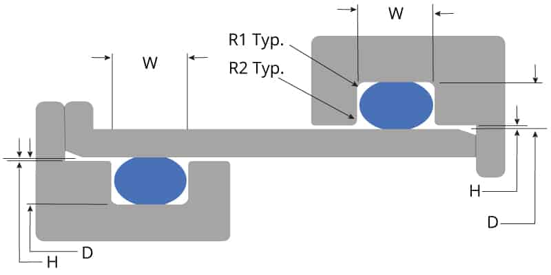


O Ring Groove Design Global O Ring And Seal
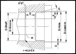


O Ring Seals Roy Mech
Our oring groove design guides list default oring groove dimensions for the most basic applications and are intended to be used with the following oring groove design considerations to engineer on oring gland to optimize specific application performance The wrong size groove makes even the best oring underperform Trust and Choose Marco Rubber & Plastics For moreQUALITY SEALS GROOVE DESIGN AND ORING INSTALLATION Outline of Training Description of common types of seals A Static seals B Dynamic seals Groove dimensions and machining considerations A General considerations B Groove design C Grooves for static vs dynamic seals D Example of determining groove dimensions Ill Determining Cross section A Piston seal BRubber Seals, Sealing Devices & ORing Seal Design Apple


O Ring Groove Design Standard As568b Seal Design Inc


O Ring Wikipedia
Home >> Seal >>ORings >> ORing Groove Design ORing Groove Design Groove Design for ORing Installation Technical Resources ORing Catalogue;ORing Design Guide HITECHSEALSCOM 3 Compound Specification Guide Prefix Material Duro Temperature Range Description N70 Nitrile 70 ± 540°C to 1°C 40°F to 248°F A general service nitrile compound for a wide range of applications including petroleum based fluids Nitrile compounds also have excellent resistance to compression set, tear and abrasion resistance N90ORings West's goal is to be recognized globally for quality, reliability and expertise in all aspects of our business Our policy is to provide a management system and a working environment that emphasize predetermined quality objectives through continual enhancement of personnel capabilities and quality awareness This system is based on continuous, permanent quality
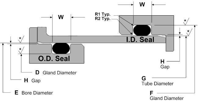


Static O Ring Design Chart Marco Rubber Plastics Custom O Rings Supplier


Oring Ehandbook
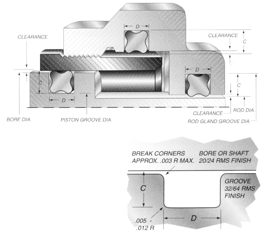
Suggested Groove Design for Quattro Seals™ Due to their unique fourlobed geometry, grooves for Quattro Seals are different than those for ORings In general, Quattro Seal grooves are deeper, as less squeeze is required to affect a positive seal Quattro Seal grooves are also narrower due to their ability to resist "spiral failureDesigning the parts of an application where orings will be applied is broadly termed "oring groove design" In order to seal properly, the oring has to deform in the application by being compressed and stretched in any number of ways The design of the groove where the oring sits plays a major role in how the oring performs its sealing role Extrusion Limits;Find Orings by size, temperature range, material type, compliance, and more Find and Buy Marco Orings Online * Recommended surface finish 16 Ra max for gases and 32 Ra max for fluids All dynamic applications to have 16 Ra max Dynamic ORing Gland Width and Depth and Diameter Default Recomendations AS568 Dash Sizes ORing CrossSection


Seal Design O Ring Design O Ring Design Guide
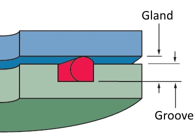


4 Common Mistakes In Designing For An O Ring Axial Face Seal Hot Topics
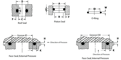
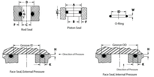
Depending on your application you can have the groove be cut in either the piston or the bore The groove shape isORing Design & Lubrication;In radial seals, the gland is defined by the Bore Diameter on the outside radius, the Groove Diameter on the inside radius, and the Groove Width in the axial direction (see schematic) Inner Diameter In order for the ORing to fit snugly in the groove, it is desirable to circumferentially stretch the ORing slightly


Buy O Rings Seals Custom Molded Rubber Engineered Plastic All Seals
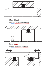


2 Design And Detail Information O Rings Stock O Ring Webshop
As568b standard oring groove design Contact Us For Assistance Or Samples Click Here and contact us today to receive a quote or if you have any questions regarding sizing × Dismiss alert The three main types of standard groove designs are Industrial Static also called Radial, Industrial Reciprocating also called Dynamic, and Face Seals also called Axial or FlangeHere you will find an Oring groove design guide to help you with your Oring gland dimensions Through our extensive research we believe that these Oring groove dimensions and fit details will provide the optimum Oring compression squeeze for your seal to prevent Oring leaks Based on the cross section (CS) of your Oring, you will choose the corresponding Oring groove depthORing Radial Axial metrical No One Two EccenCross Clearance Backup Backup Backup Groove tricity Section Radial Axial Inches % Inches % Max Rings Ring Rings Radius Max ORing Gland Design For Static Seals Note Table A contains general sealing guidelines More specific information is available throughout this guide


Llis


O Ring Groove Design Daemar Inc
Oring groove design guides offer default dimensional guidance on the most basic oring groove design applications The best orings are useless without the right groove design which becomes increasingly important the more demanding the application environment Review the general oring groove design considerations before moving onto the specific oring gland design typeFace Type Seals The face seal design chart below explains the hardware dimensions to use for an Oring seal when the groove is cut into a flat surface For designing systems which contain internal pressure, like the example below, the groove's outside diameter (OD) is primary, and the groove's width then determines the inside diameterOring housing data for axial and triangular sealing applications Oring housing data for piston and piston rod sealing applications Oring housing data for piston and piston rod sealing applications Type C Type D (0059) (0063) (0070) (0079) 2,40 (0094) 250 (0098) 2,62 (0103) 3,00 3,50 (0138) 3,53 (0139) 4,00 (0157) 5,00 (0197) 5,34 (0,210) (0224) 6,99 (0275) (0331) internal


O Rings For Oil Gas Applications Trelleborg


Groove Design Gland Design O Ring Groove Gland Design
ORING DESIGN QUICK REFERENCE This design quick reference guide is intended for use in specifying Oring and groove dimensions for static applications with pressures less than 1500 psi The guidelines are for the nominal condition The minimum and maximum conditions should also be checked This requires looking at the dimensionally largest possible Oring in the smallestIn a static radial seal application the Oring is squeezed between the inner ID and the outer OD surfaces of the Oring, with no relative motion between parts of the gland that come in contact with the Oring The table on our detailed information page lists recommended dimensions for static radial oring glands by AS568A Oring dash numbers Orings and seals in static radialGroove design guide for static oring face seals provides default recommendations on width, depth, diameter and more for basic applications Oring face seals are used in a variety of applications, including bolted flanges or removable lids Simple selection tool to


Groove Design Quad Ring Seals Minnesota Rubber Plastics


O Ring Grooves
O Ring Groove Design Standard Dovetail grooves are used to hold the Oring inplace on a face seal groove during during assembly and maintenance of equipment An undercut or dovetail groove has proven beneficial in many applications to keep the oring in place This is an expensive groove to machine, however, and thus should be used only whenO'ring Groove Design As important as the o'ring seal itself is the groove that the o'ring seats into The groove must be designed to accommodate not just the o'ring size, but also its intended usage;ORING GROOVE DESIGN Designing the parts of an application where orings will be applied is broadly termed "oring groove design" In order to seal properly, the oring has to deform in the application by being compressed and stretched in any number of ways The design of the groove where the oring sits plays a major role in how the o


O Rings O Yeah How To Select Design And Install O Ring Seals Tarkka


O Ring Groove Design Guides Engineering Quick Reference
ORing Handbook Parker Hannifin ORing Diision Europe ORing Handbook Parker Hannifin ORing Diision Europe Preamble Sealing technology by ParkerPrädifa The Engineered Materials Group of the Parker Hannifin Corporation is the worldwide leader in the field of designing, developing and manufacturing sealing systems, vibration dampers, EMI shielding systems and heatCauses of ORing Failure;Oring groove design is a key consideration in the oring selection process Browse design considerations and recommendations for static face seals, metric orings, static dovetail orings, static rodpiston orings and dynamic rodpiston orings Once you find the right oring groove design you can easily order online from the world's largest


O Ring Groove Design Guides Engineering Quick Reference


O Rings O Yeah How To Select Design And Install O Ring Seals Youtube


Designing Axial Static O Ring Grooves To Industry Standards Grabcad Tutorials


American Seal Packing General Design And Gland Dimensions


Untitled Document


What Is An O Ring Selection Material And Storage Barnwell


O Ring Groove Design Global O Ring And Seal


Nbr O Ring Groove Design Low Temperature Resistance O Ring Customized Oil Seal O Ring Manufacturer Buy Oil Seal Ring O Ring Groove Design Low Temperature Resistance O Ring Product On Alibaba Com


1


O Ring Groove Design Global O Ring And Seal


Dynamic Rotary Gland Design Dynamic O Ring Gland


O Rings Designing


Ficient Design Static O Ring Groove Design Mechanical Engineering


How To Design An O Ring Groove Vizeng


Quad Ring Groove Design Daemar Inc


What You Need To Know About Designing Axial Seals Hot Topics


Standard Dovetail Grooves Dovetail Groove Engineering Design Guide
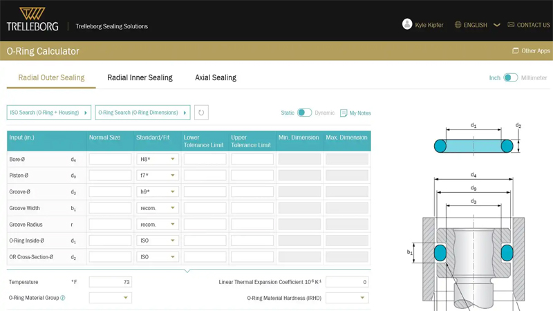


O Ring Calculator Trelleborg Sealing Solutions
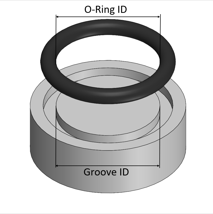


O Ring Design Considerations Marco Rubber Plastics Custom O Rings Supplier
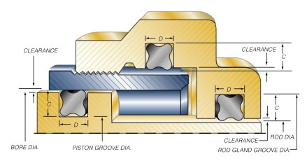


Groove Design Quad Ring Seals Minnesota Rubber Plastics


Sealcalc
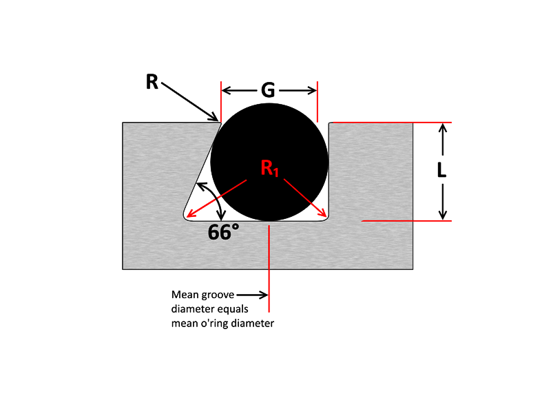


O Ring Groove Design Sealing Australia


Ruander Com Quick O Ring Groove Design Guide
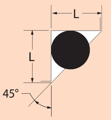


Triangular O Ring Grooves Mechanical Seal Engineering Eng Tips
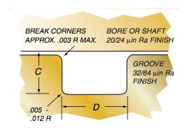


Groove Design Quad Ring Seals Minnesota Rubber Plastics


4 Common Mistakes In Designing For An O Ring Axial Face Seal Hot Topics
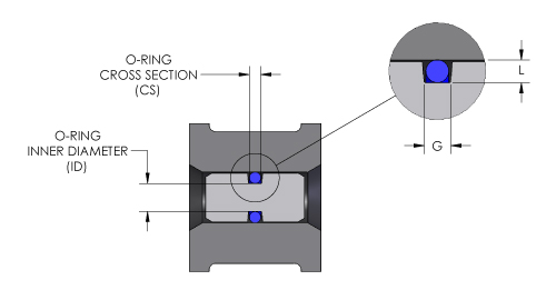


O Ring Groove Design O Ring Groove Dimensions Mykin Inc
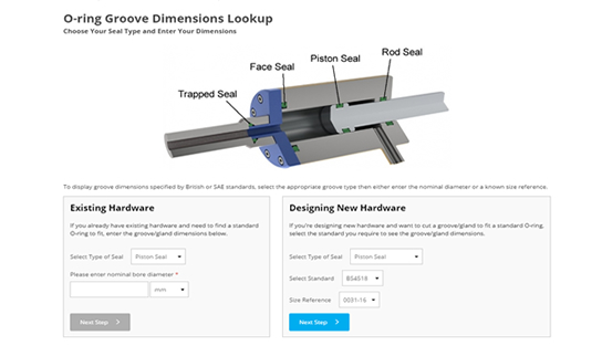


O Ring Groove Dimensions Calculator Precision Polymer Engineering


O Ring Groove Design Seal Design Inc


Untitled Document


O Rings O Yeah How To Select Design And Install O Ring Seals Tarkka


Efunda Introduction To O Rings


Designing Axial Static O Ring Grooves To Industry Standards Grabcad Tutorials


O Ring Groove Design Face Seal


O Ring Installation Design And Specification Static Cylindrical Installations Engineers Edge


O Ring Groove Design Global O Ring And Seal


O Ring Groove Chart


Sae J1453 O Ring Face Seal Groove Size Chart Knowledge Yuyao Jiayuan Hydraulic Fitting Factory


Design Of Oring Seals Design Of Oring Seals


Mating Ring An Overview Sciencedirect Topics
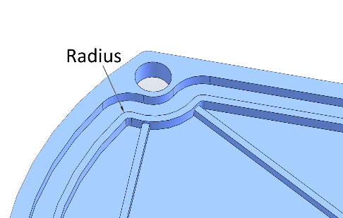


4 Common Mistakes In Designing For An O Ring Axial Face Seal Hot Topics


Using An O Ring In Non Circular Grooves


Oring Ehandbook


Seals Eastern O Ring Rod Seal Design Guideline
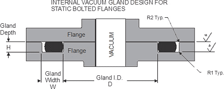


Static O Ring Face Seal Groove Design Guide


O Ring Groove Design Guides Engineering Quick Reference


Metric O Ring Groove Design Reference Guide


Seal Design O Ring Design O Ring Design Guide
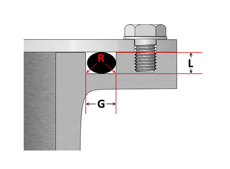


O Ring Groove Design Sealing Australia


1
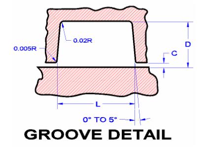


Seals Eastern Plug Seal O Ring Design Guideline


Oring Ehandbook
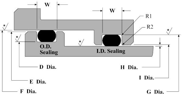


Dynamic O Ring Design Chart Marco Rubber Plastics Custom O Rings Supplier


How To Design An O Ring Groove Vizeng
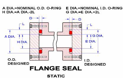


Seals Eastern Flange Seal O Ring Design Guideline


Oring Ehandbook


O Ring Groove Design Metric Seal Design Inc


1
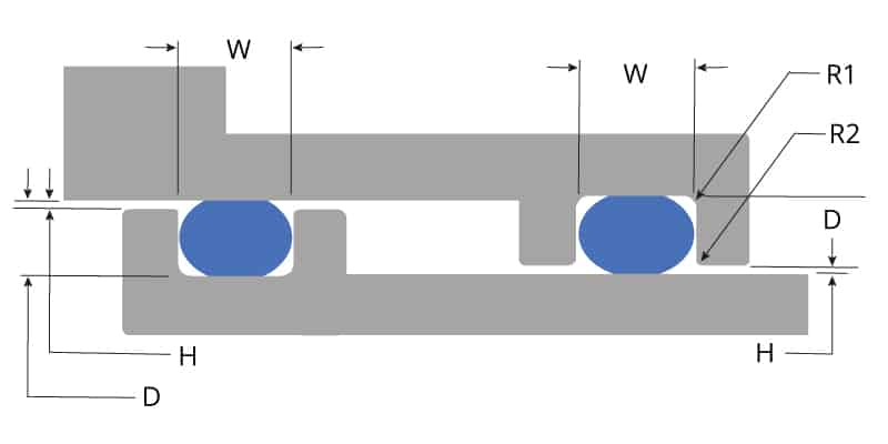


O Ring Groove Design Global O Ring And Seal


1
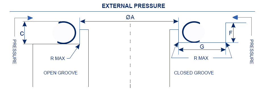


Types Of Metal Seals Guide To Metal Seal Selection O Rings Barnwell
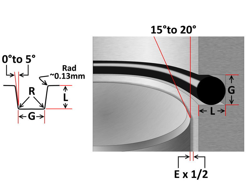


O Ring Groove Design Sealing Australia
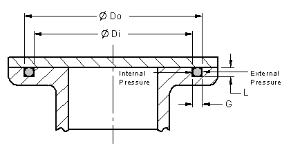


O Ring Installation Design And Specification Static Flange Application Engineers Edge


O Rings An Overview Sciencedirect Topics


O Ring Groove Design Standard As568b Seal Design Inc


Parker S O Ring Selector App Youtube
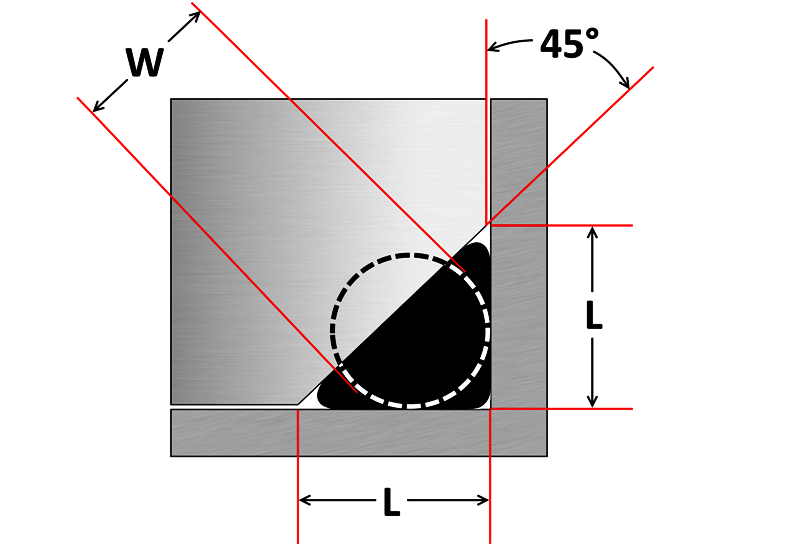


O Ring Groove Design Sealing Australia
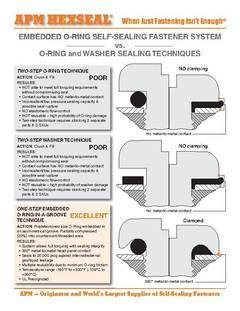


Anyone Have Experience Designing An Asymmetrical O Ring Groove Under A Bolt Head Mechanical Engineering General Discussion Eng Tips


Design Of Oring Seals Design Of Oring Seals
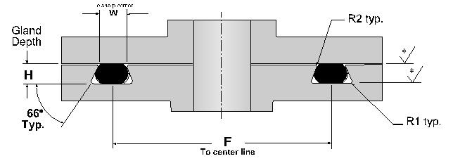


Dovetail O Ring Groove Design Guide A Basic Recommendations


Static Axial Internal Pressure Gland Groove Design
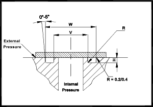


O Ring Seals Roy Mech
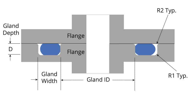


O Ring Groove Design Global O Ring And Seal
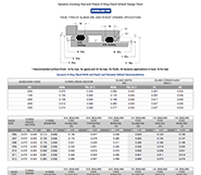


O Ring Groove Design Guides Engineering Quick Reference


O Ring Cross Section O Ring Groove Design Data
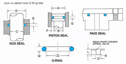


O Ring Groove Design


